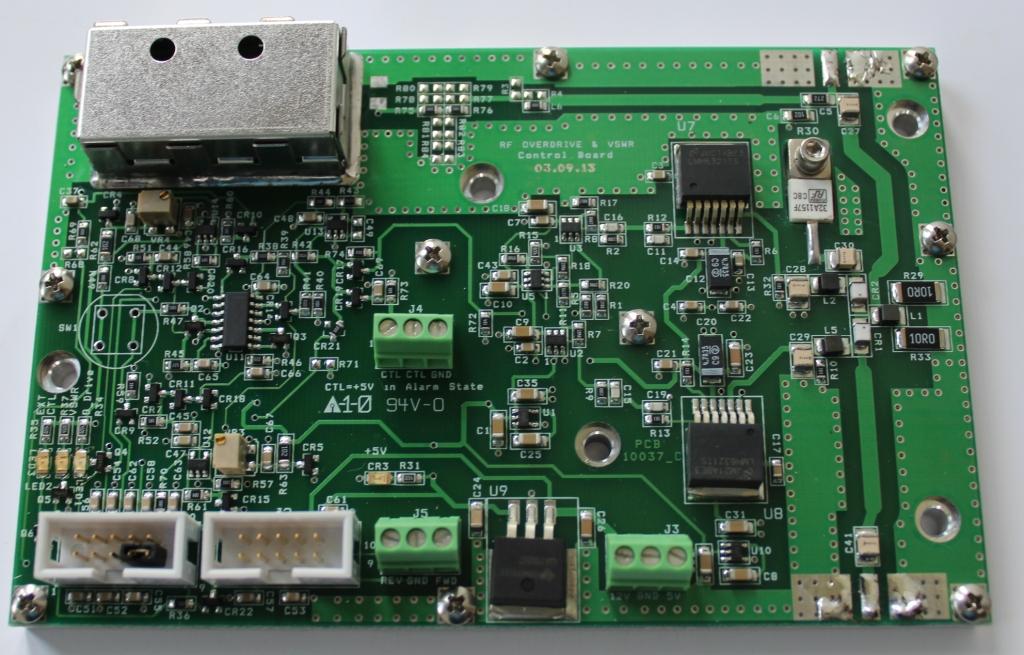
RF Overdrive and VSWR are the leading causes of RF transistor failure for our RF pallet customers. When too much RF level enters an RF transistor the transistor often fails in a few micro seconds; even if it’s one of the new XR LDMOS transistors. When an amplifier fails to produce the expected output power in an elevated VSWR the customer solution is often to increase the input drive instead of investigating the problem. This situation often results in RF overdrive and destruction of the RF device from a combination of VSWR and overdrive conditions
This model ODVSWR-PIN30W is a 50 to 400MHz overdrive/VSWR protection relay. It uses an RF detector to switch microwave pin diodes and remove RF power when preset VSWR/RF OVERDRIVE levels are exceeded. Shutdown is accomplished in less a 1 microsecond. The source is switched to a 50 ohm termination which minimizes damage risk to the exciter and the amplifier. This protection board can handle RF overdrive hits up to 65W CW.
Most protection circuits employed in commercial equipment monitor for excessive output power through a directional coupler located at the output of the amplifier. Here a microprocessor makes a decision to disable bias and or cut DC supply. By the time the microprocessor makes its decision the transistor is usually gone. Our protection circuit uses high speed op amps and pin diodes to accomplish shutdown at the required speed to protect the transistor every time.
Extensive destructive testing has been performed with the new LDMOS BLF178P and BLF574. During 1 test we drove 20 watts into a BLF178P FM pallet which is rated for 2.5 watts and the protection worked every time; including “instant on” where we switched the DC source to the driver on and off.
This product is designed to work with FM and NTSC analog/8VSB/DVB digital modulation. The circuit uses high power microwave diodes forward biased at 200ma each to insure that minimal distortion is introduced on the input signal.
SPECS:
- DC input nominal; 12VDC @ 0.5A
- Average on state power 30W
- Maximum OVERDRIVE rating without damage: 65W
- Switch time: less than 1 microsecond
- Frequency range: 50 to 400MHz
- Size: L x W x H inches: 5.345 x 3.500 x 0.9
- Off state isolation 30 to 150MHz: 30dB
- Off state isolation 150 to 250MHz: 25dB
- On state loss less than 0.25dB
- Trip level: adjustable 0.75 to 30 watts.


